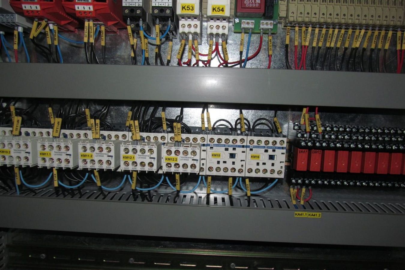
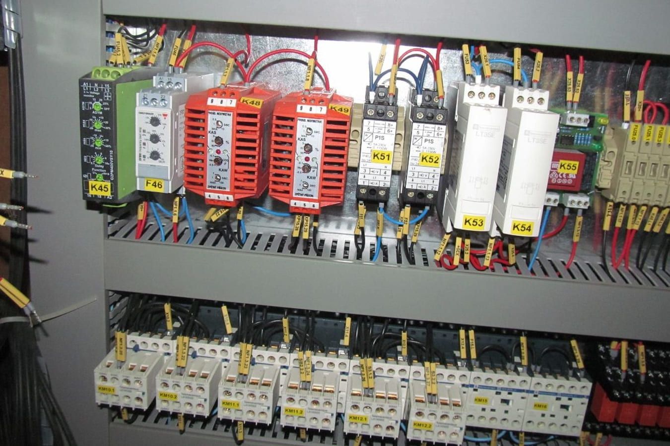
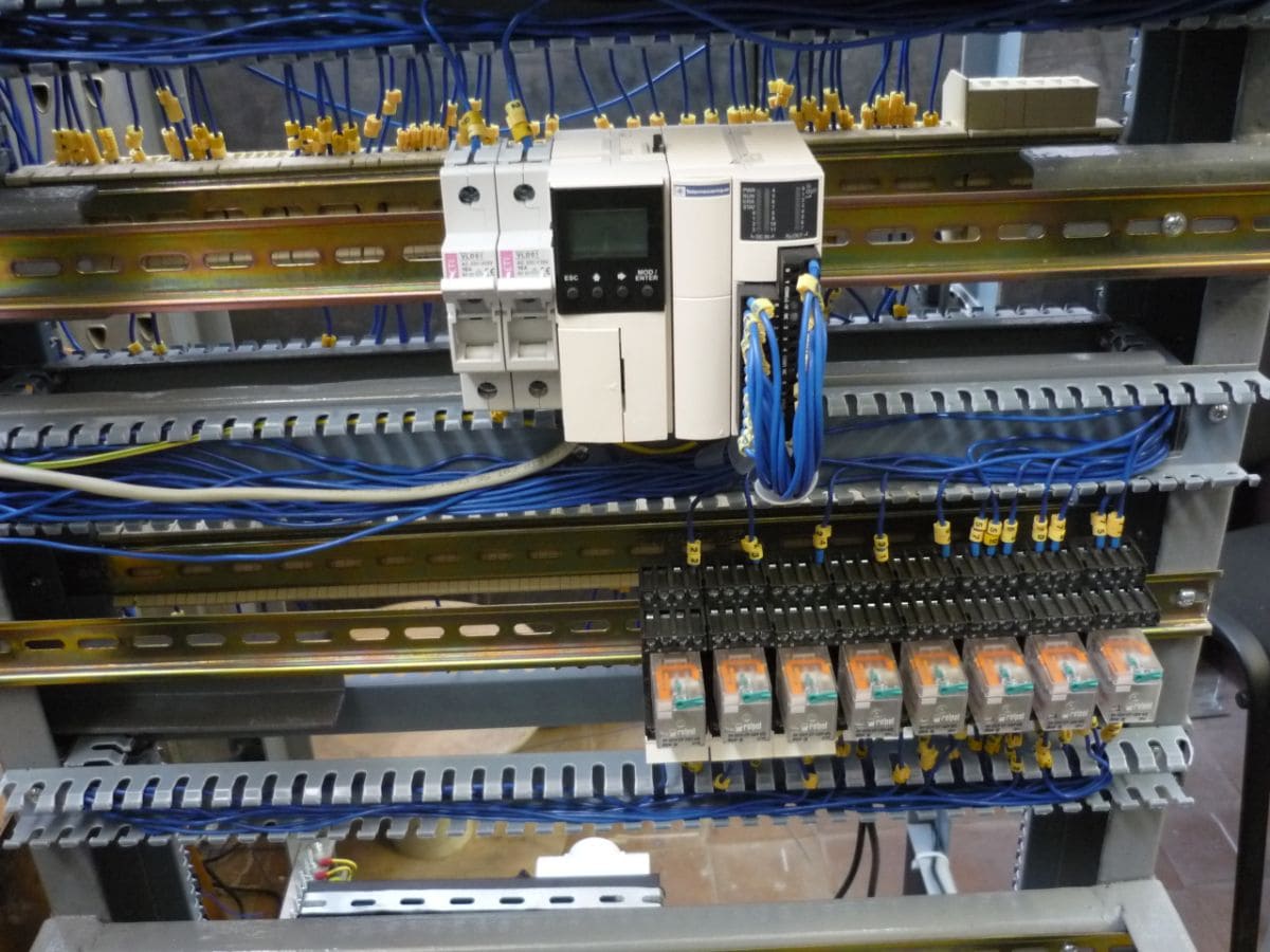
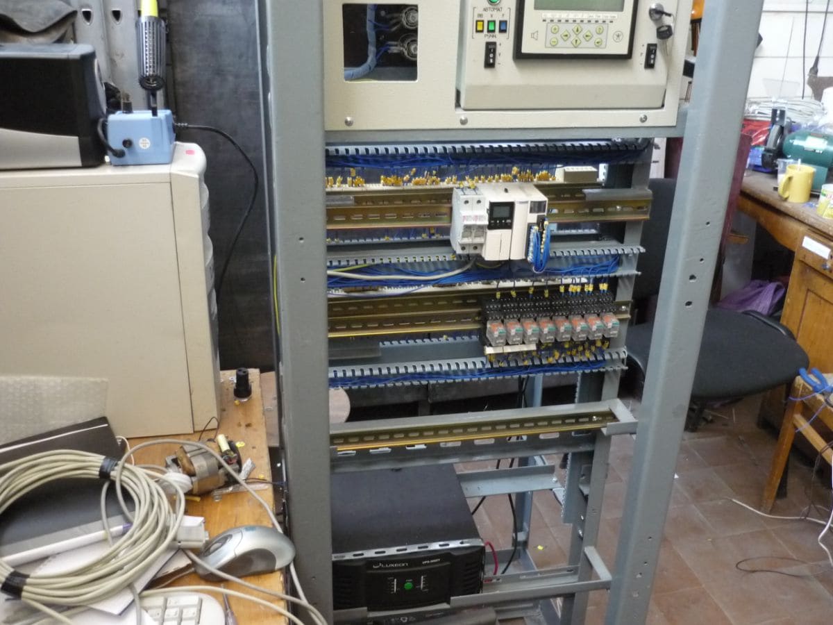
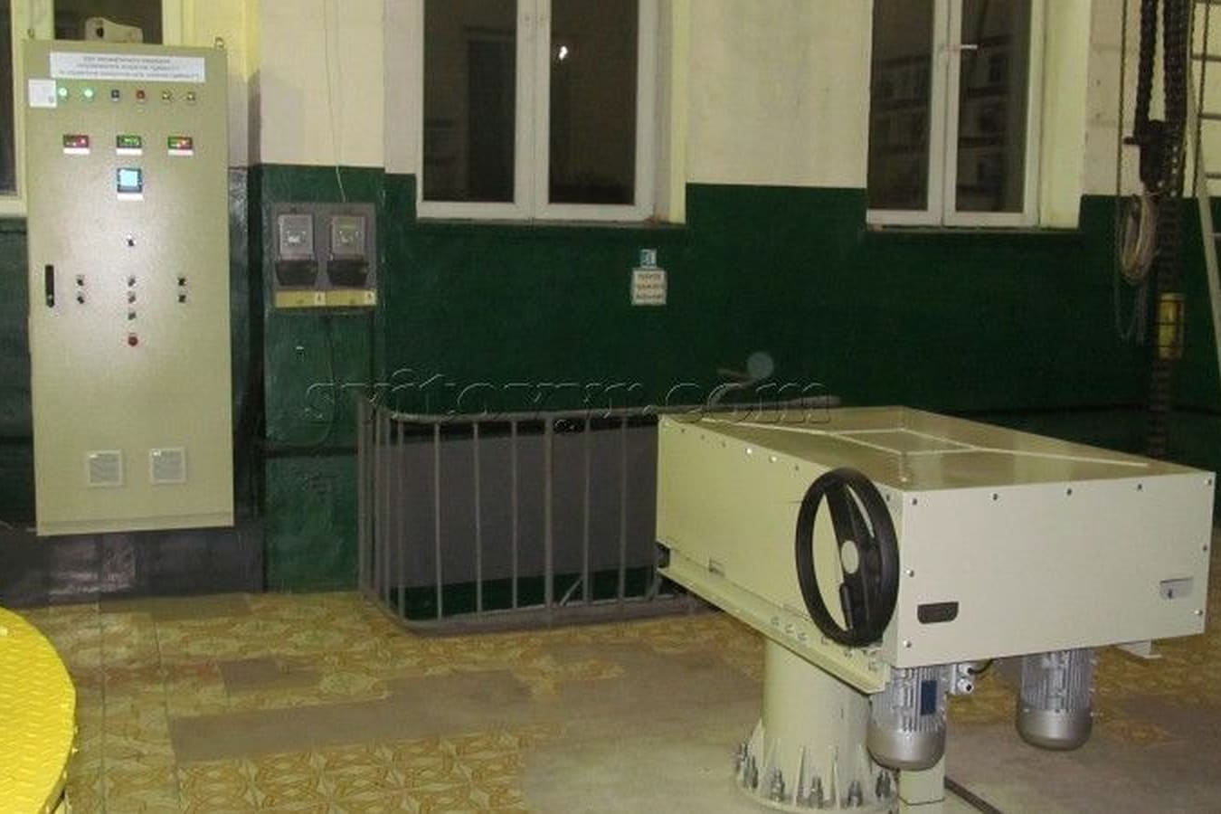
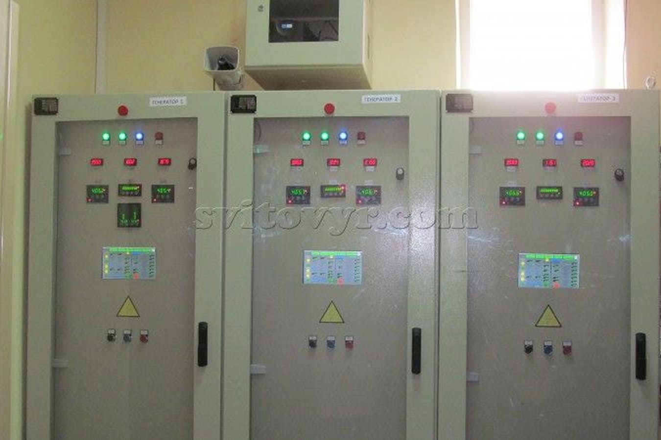
implemented projects

Bilynska HPP

Bilyn hydroelectric power station is located in Zakarpattia region.
630 kW single-generator, equipped with an induction generator for 10 kV. 
The level change between the upper and the lower reaches is 100 m. Renovation included replacement of the deflector drives of isolation valves.
Hydraulic power pack has been installed. High-voltage cells have been replaced.
Vacuum switches, microprocessor protection and 10 kV unregulated compensation cell have been applied.
The uninterruptible power supply was established by from two UPS units and a diesel generator.

A connection with the water intake established by means of optical fiber Protection has been installed to protect the grids from obstruction with slob ice and freezing in winter time. 
Video surveillance has been installed. 
HMI (Human Machine Interface) has been installed that enables the operator to manage and adjust the operation of the hydroelectric power station. 
The operation of the station is programmed by PLC (Programmable Logic Controller), it is fully autonomous, manual operation is also possible. 
Archive data of the current indicators and of the values exceeding the warning/emergency values and commutation count make it possible to predict future station operation and conduct timely revisions of the equipment. 
Personnel safety and environmental protection received scrupulous attention.


IMPLEMENTED PROJECTS

Bodnarivska HPP

Bodnarivka hydroelectric power station has two 300 kW synchronous generators, the established capacity is 600 kW. Generation voltage is 0.4 kV. An automatic operation system has been installed. The main device for station control is a Programmable Logic Controller (PLC). Nowadays PLCs are applied to quickly establish control systems. 

TWIDO controller from Schneider-Electric (France) that is designed for small and medium automation is used, which fits the requirements of the given system.

PLC receives:

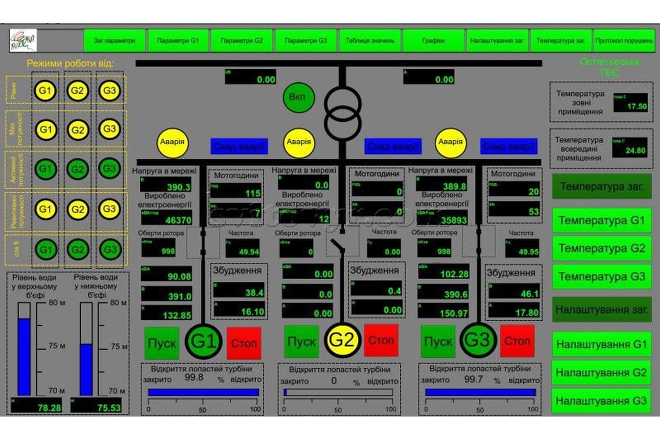
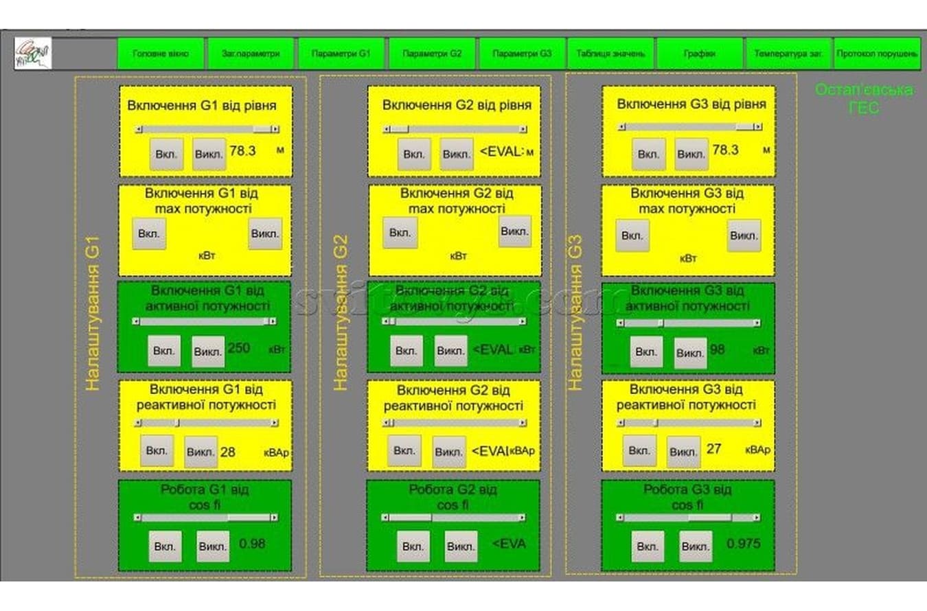
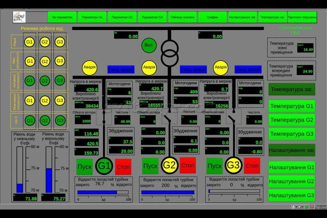
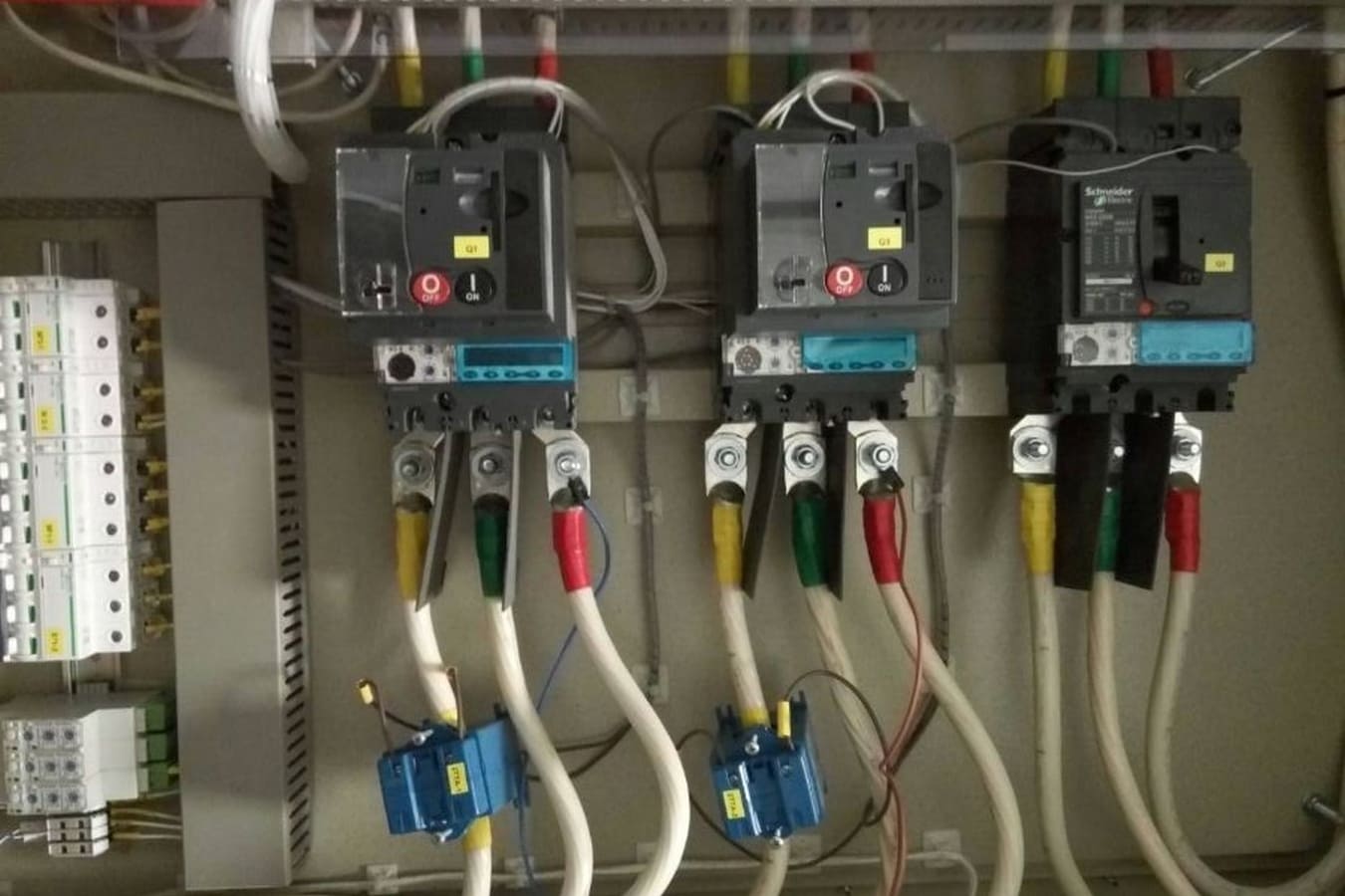
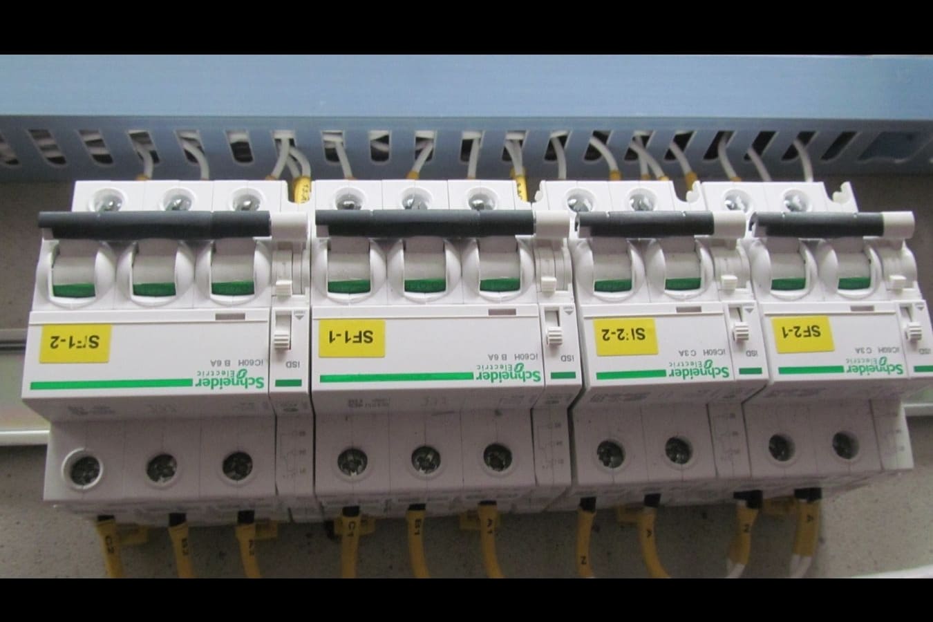
- to its discrete inputs: information from monitor control machines (system start and pause, etc), from additional contacts of commutation devices and from the automatic synchroniser on the possibility of connecting generators to the network and other discrete sensors; 

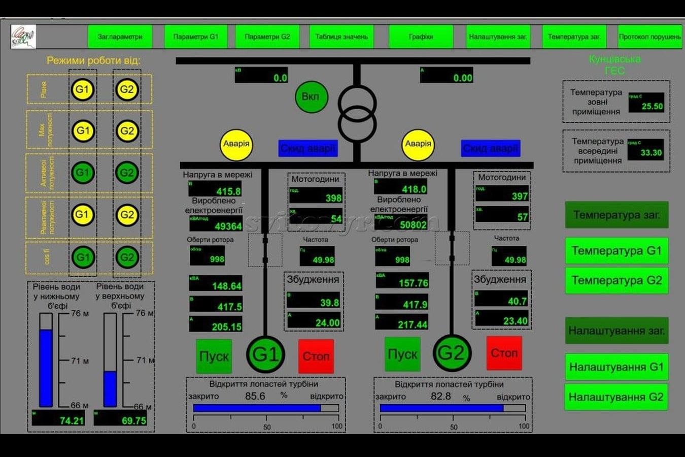
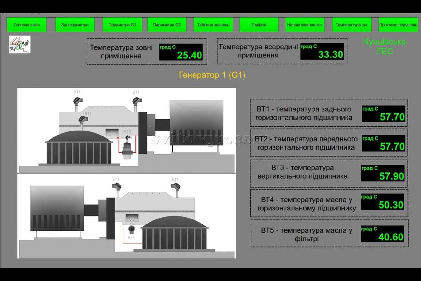
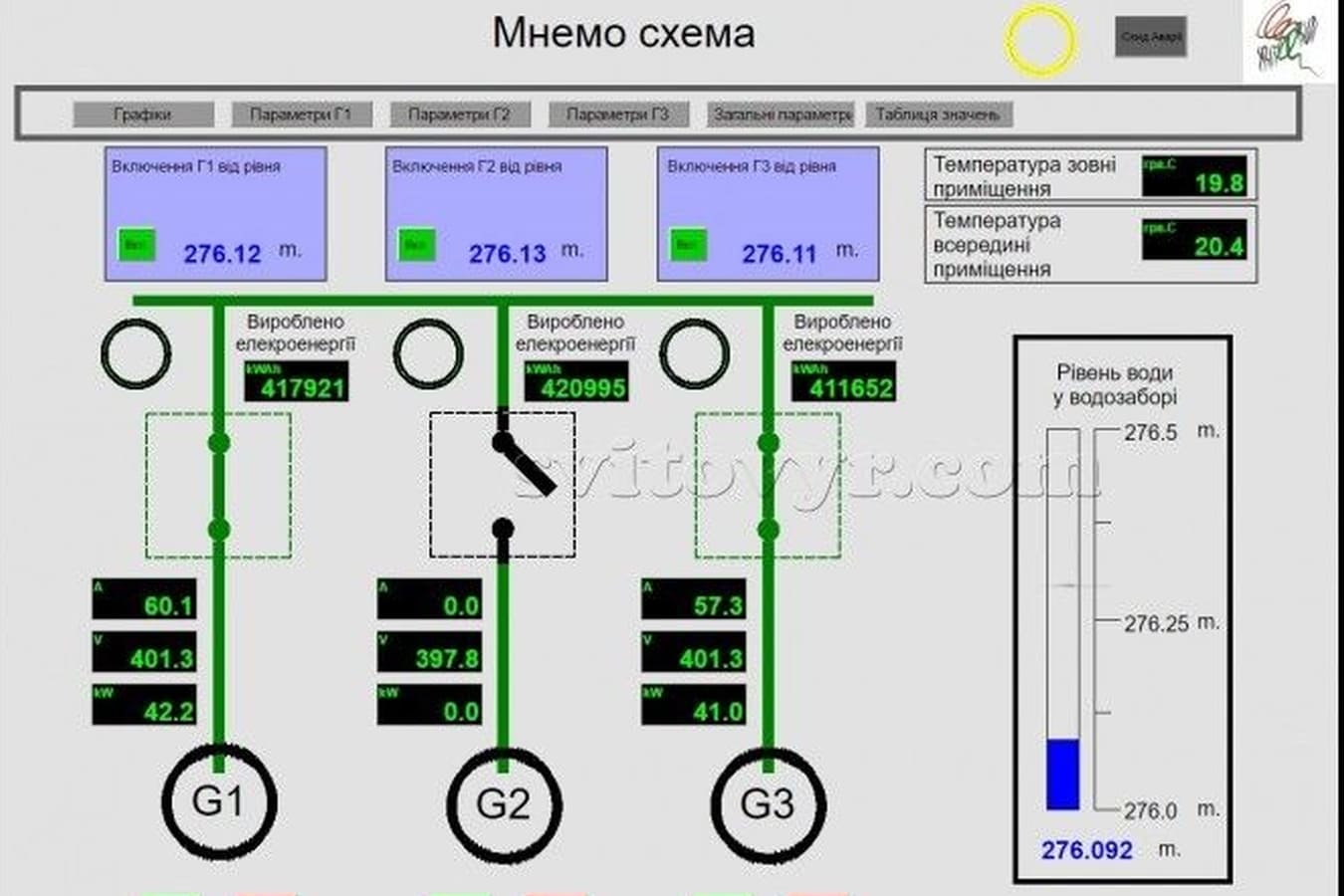
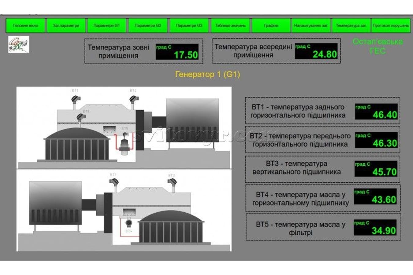
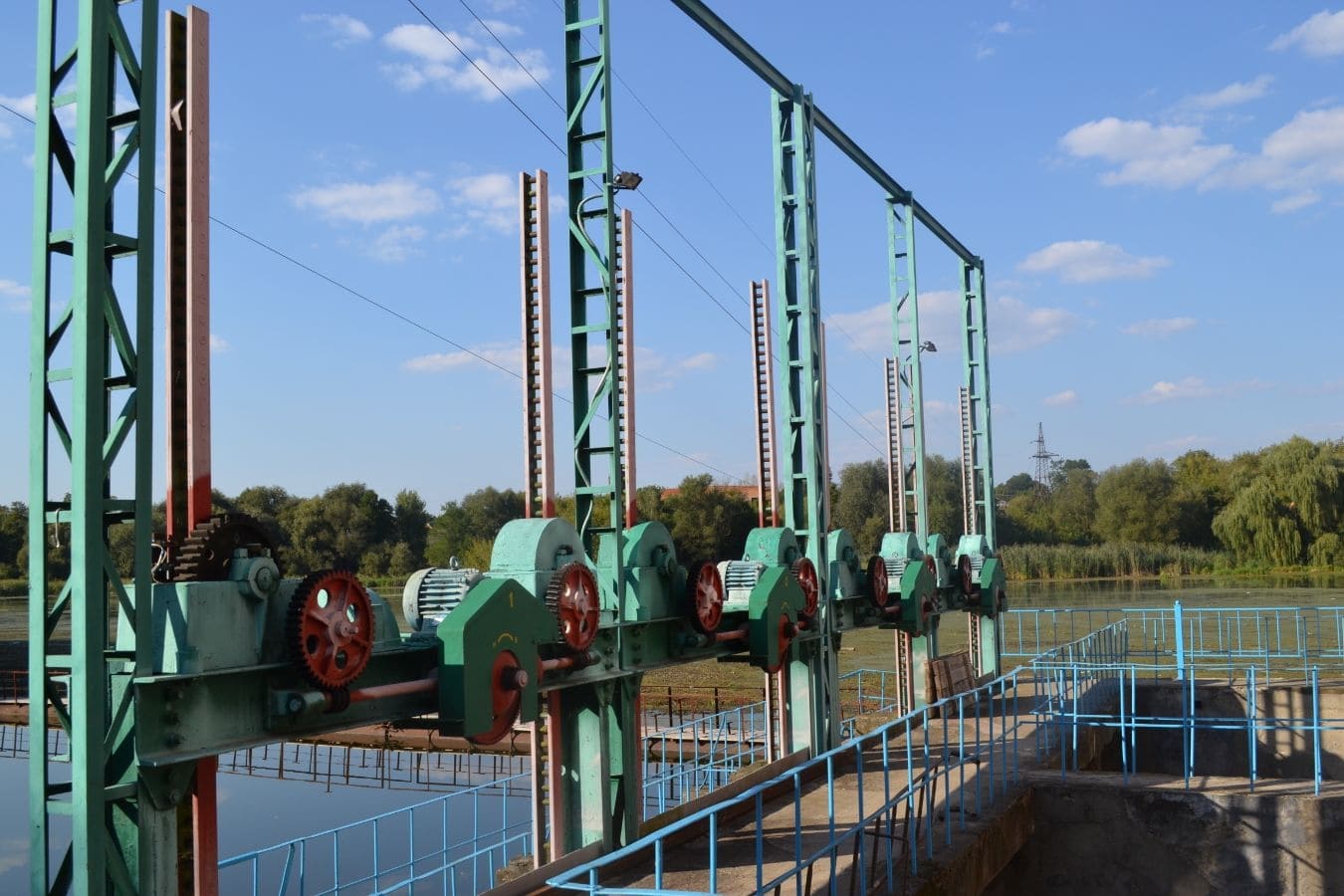
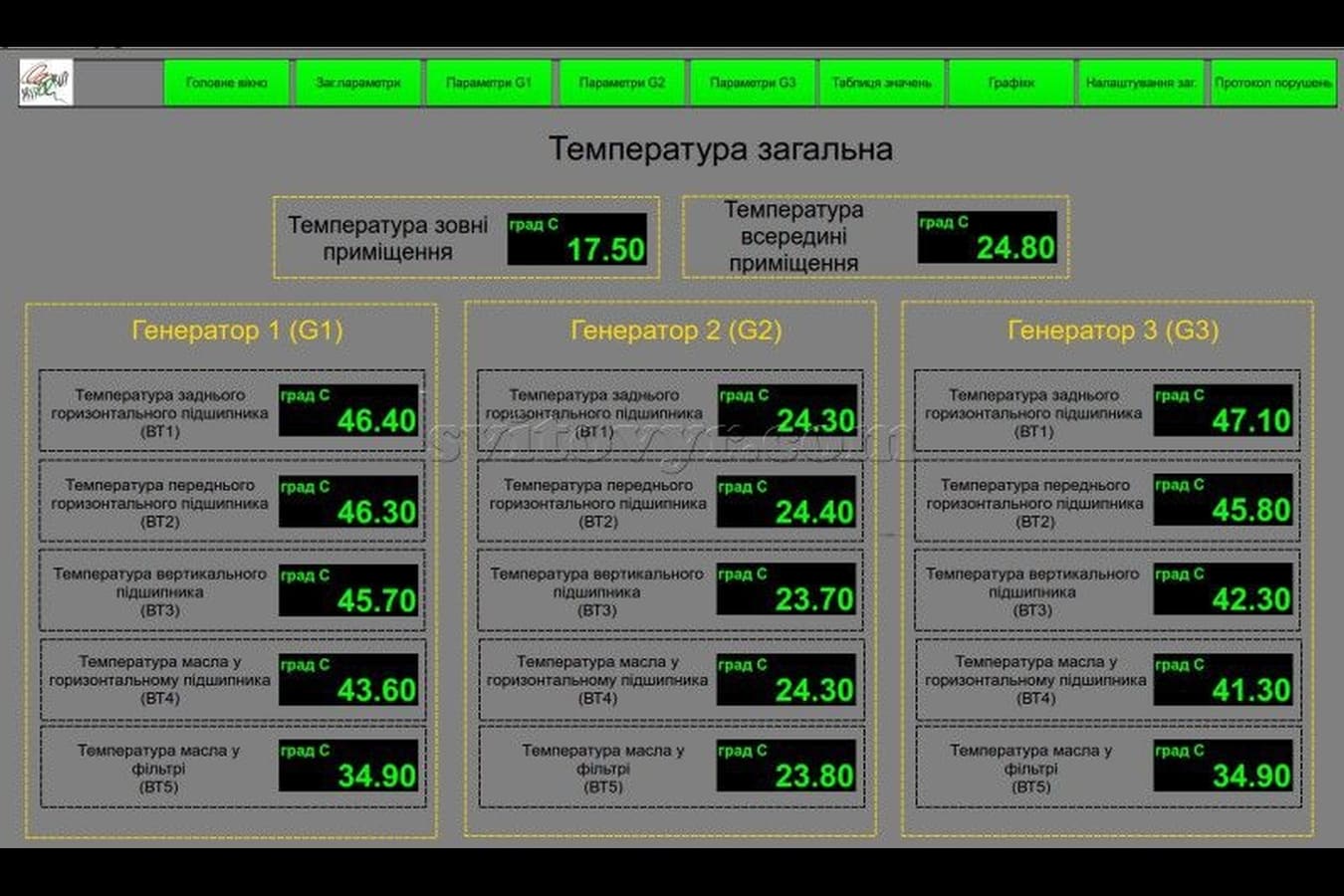
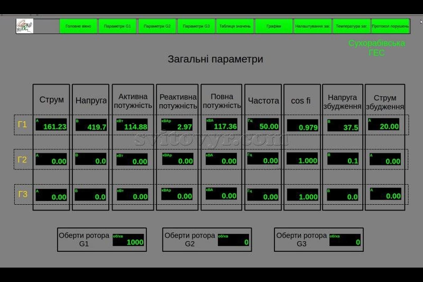
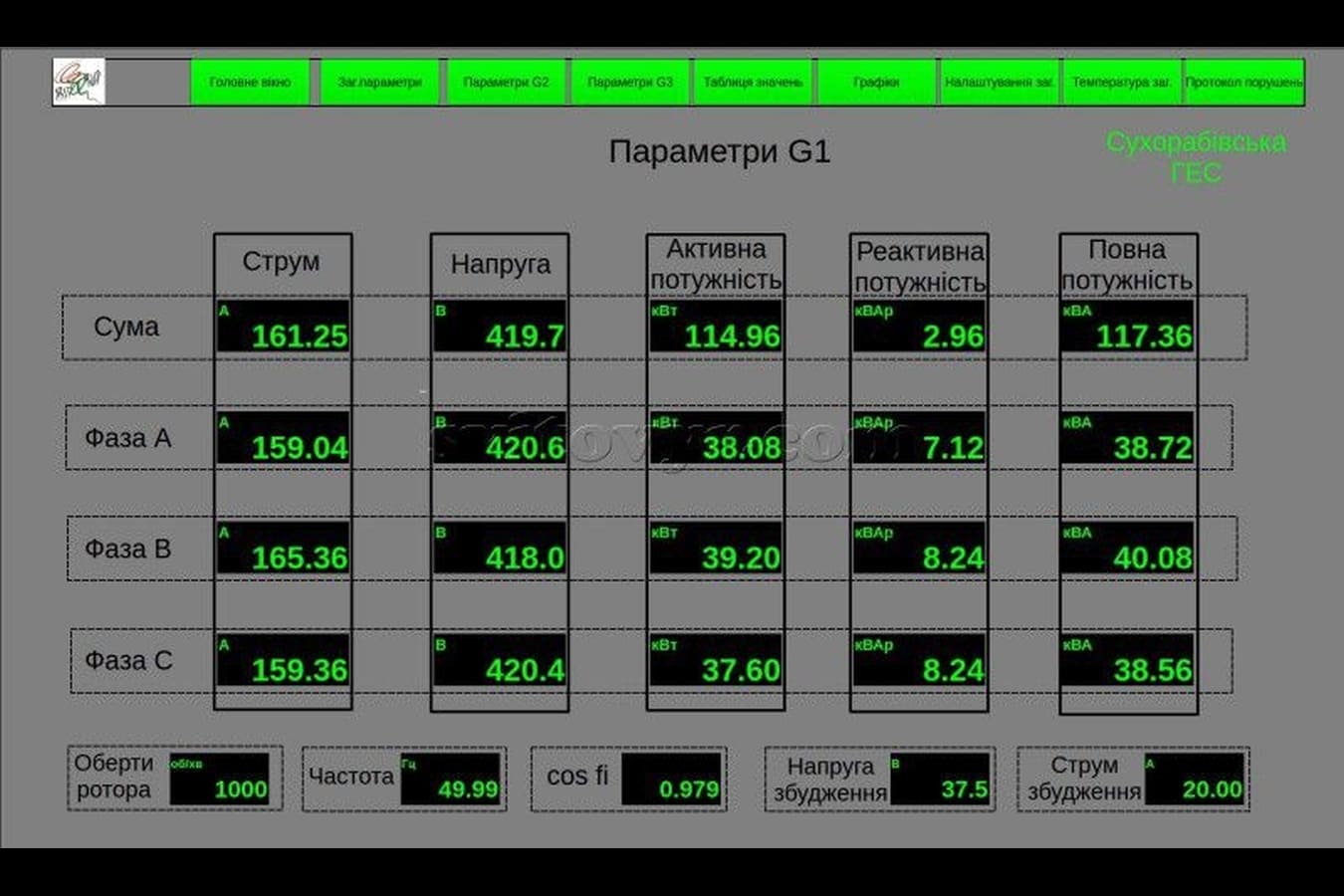
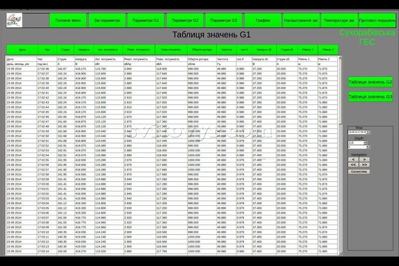
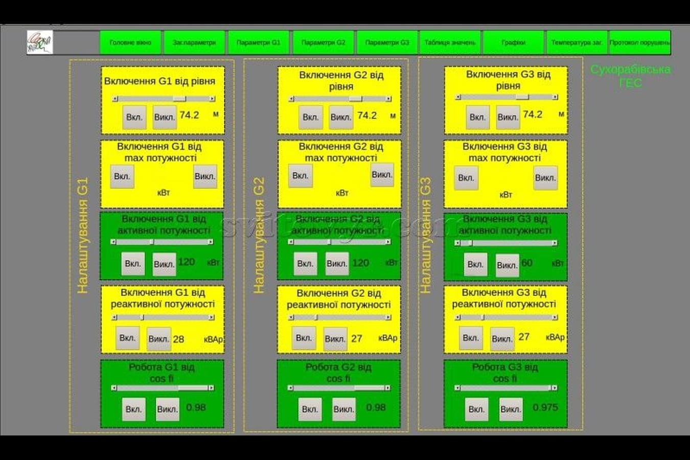
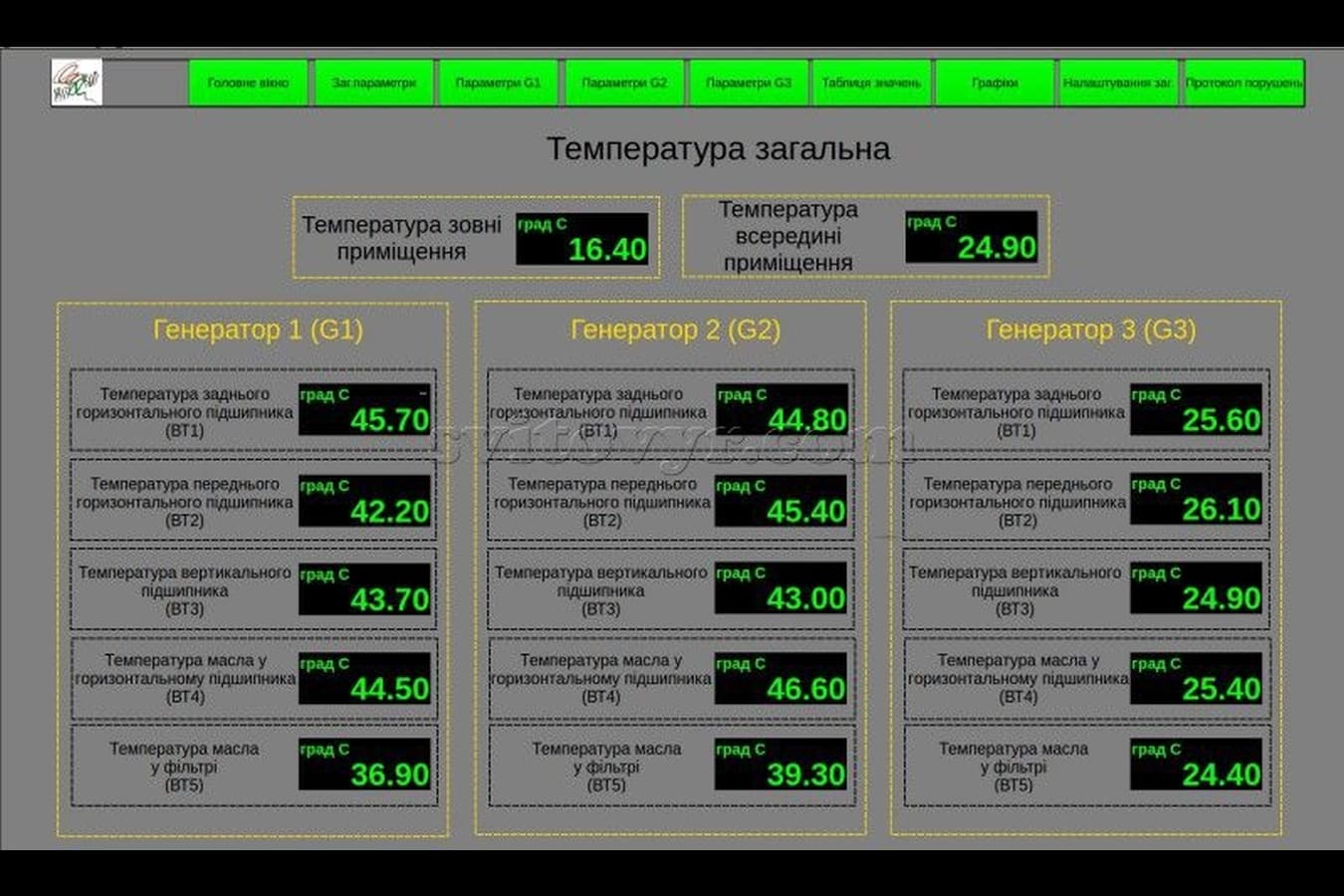
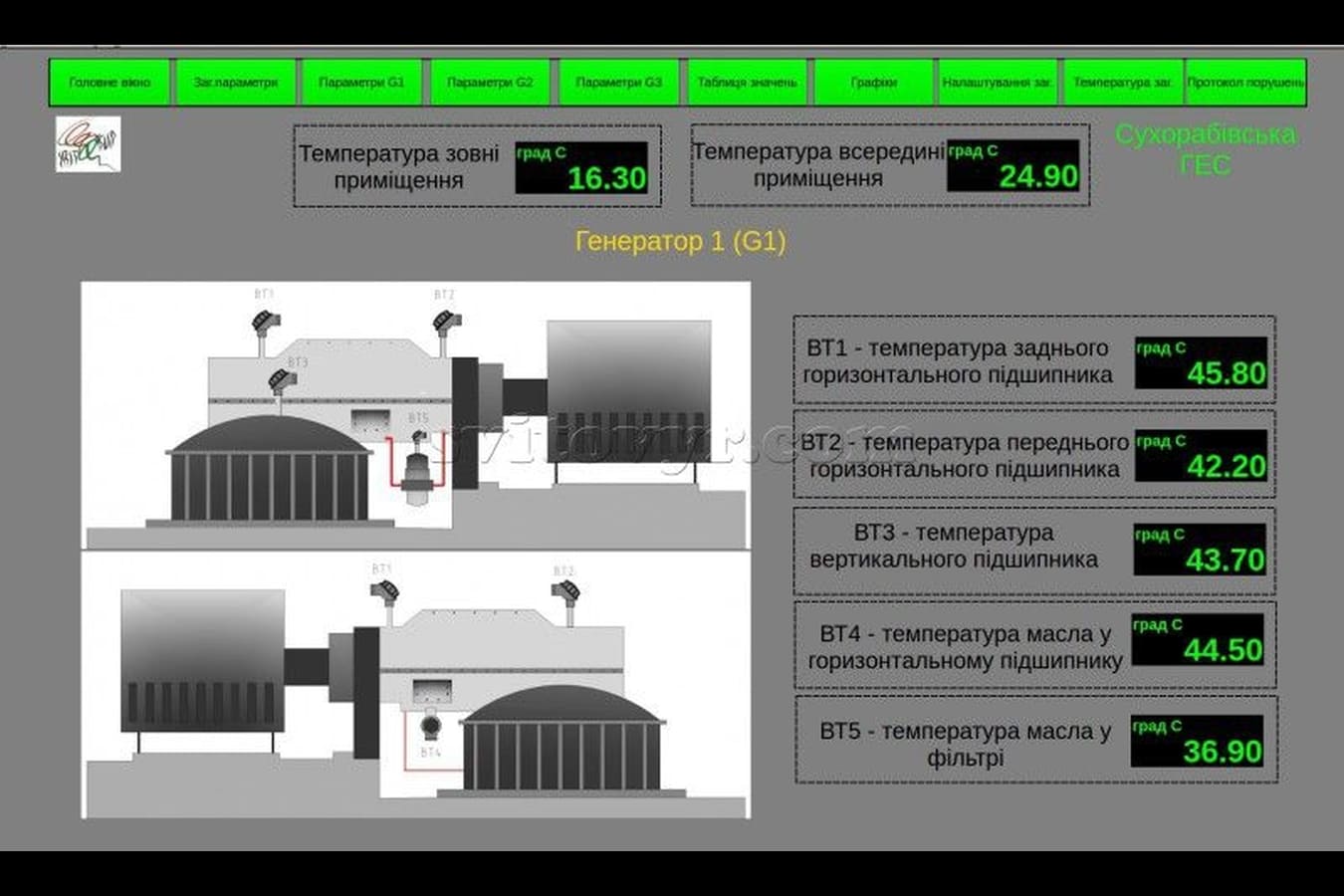
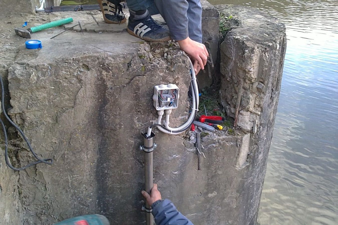
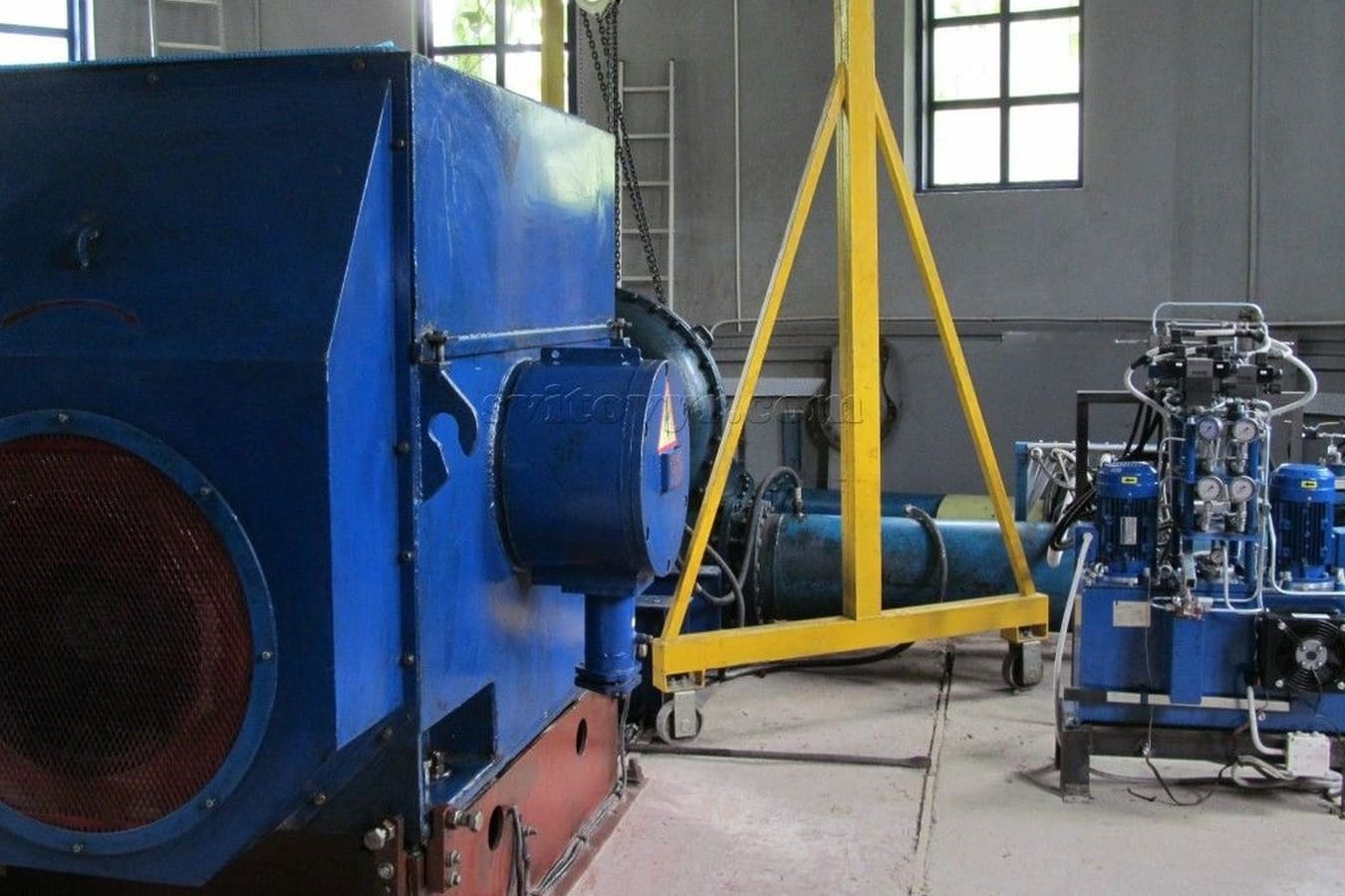
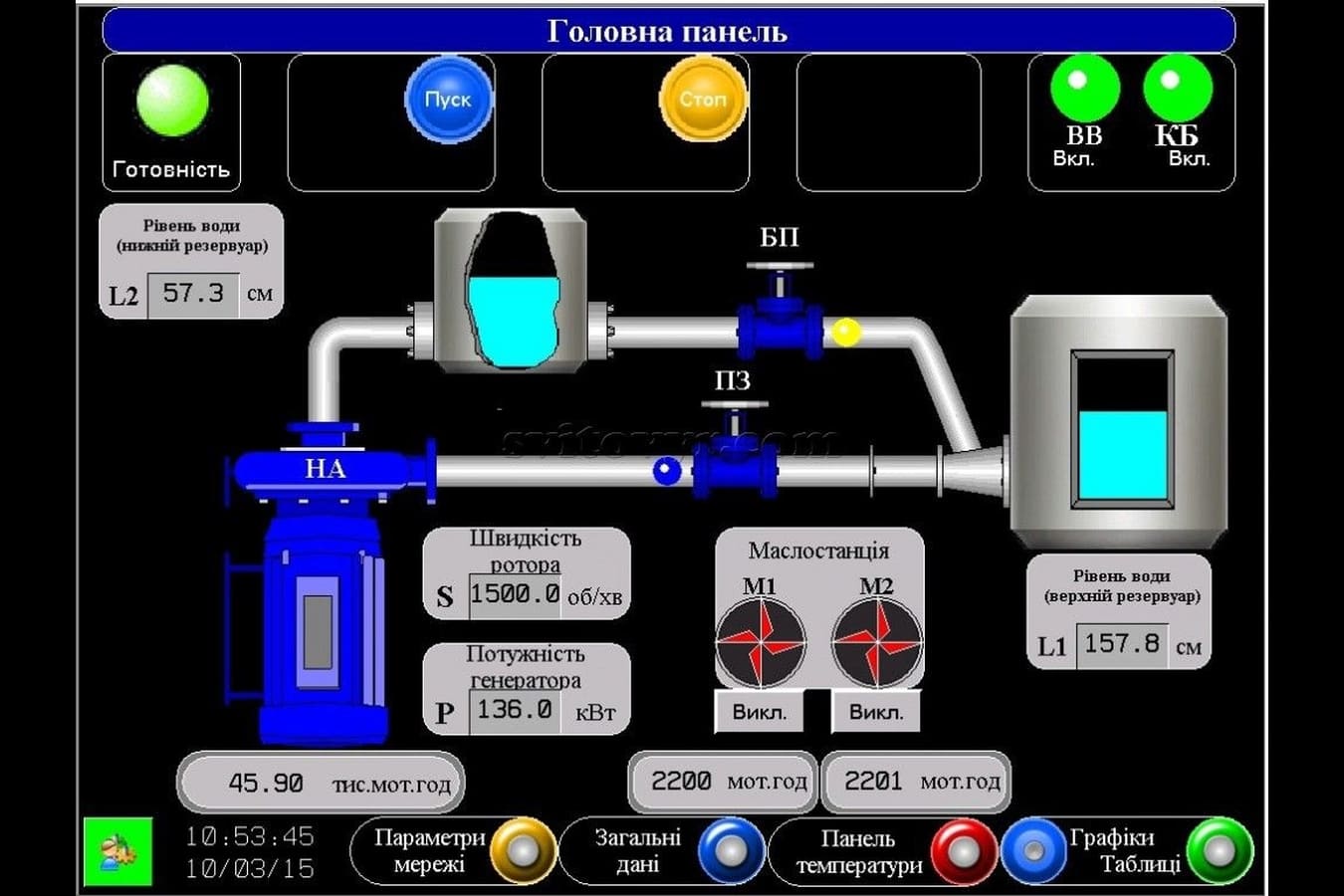
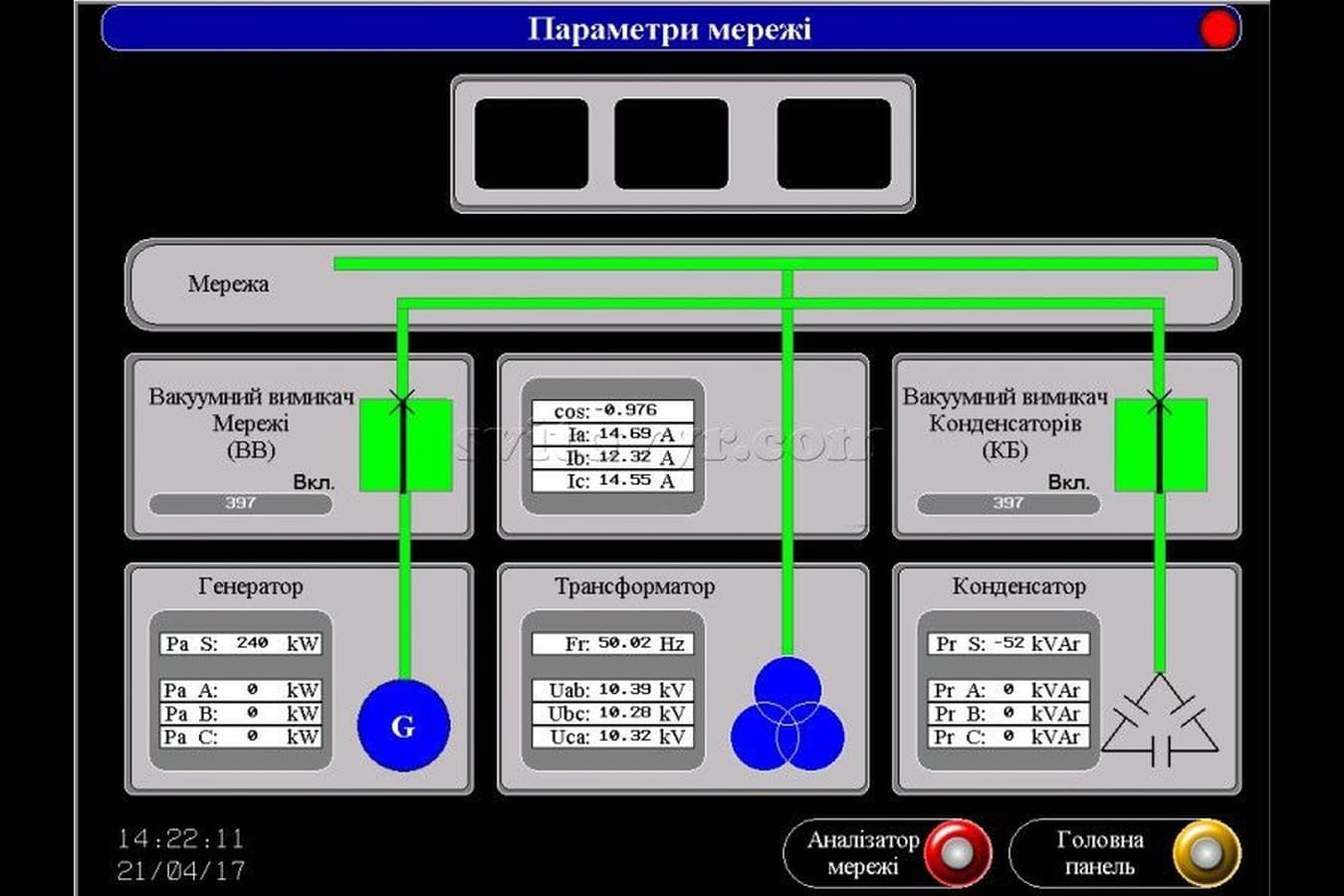
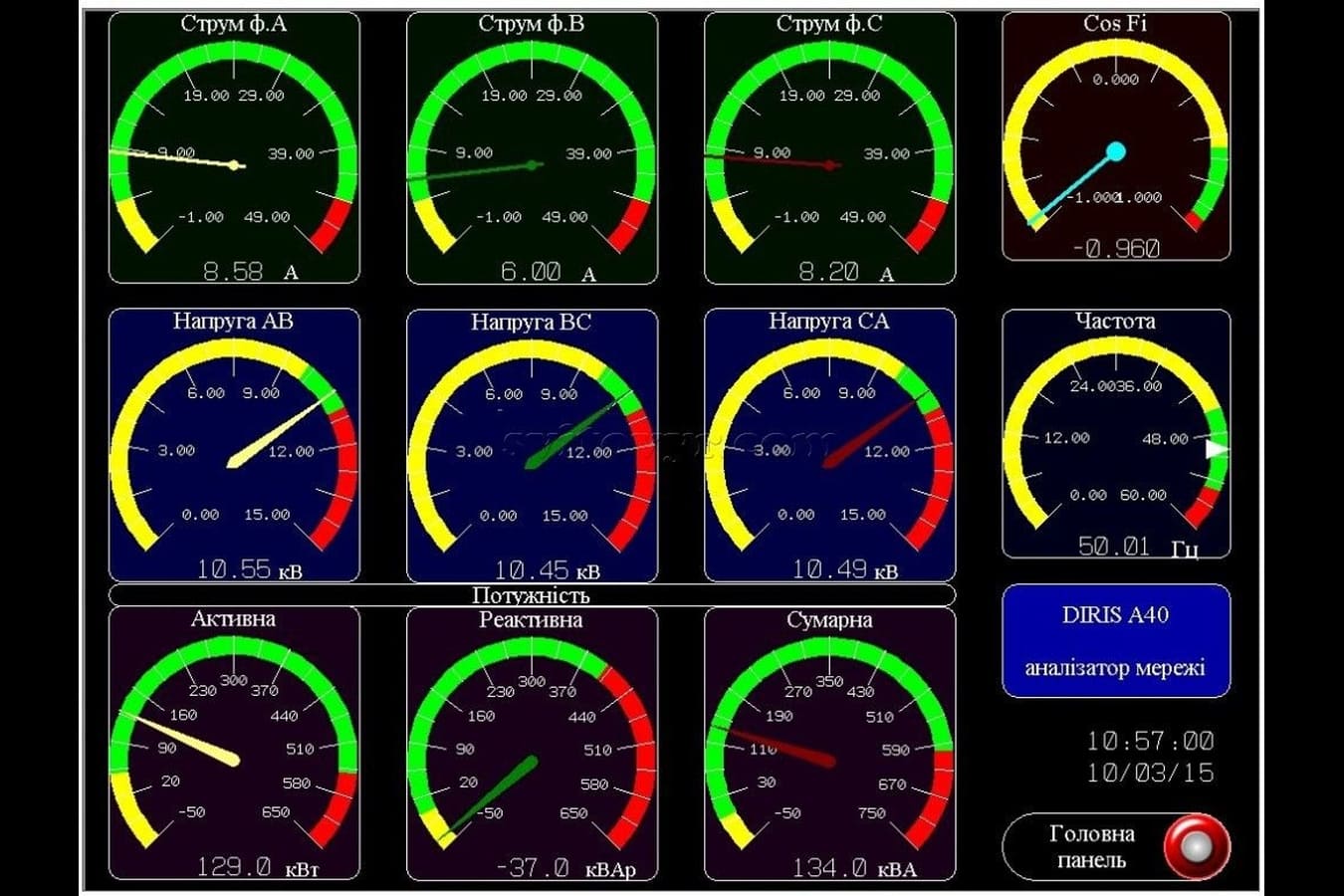
- to its analogue inputs: information on the voltage values and generator excitation currents, temperature of generator stators and water level values; 

- to its rapid action discrete inputs: information on the frequency of generator rotor rotation; 

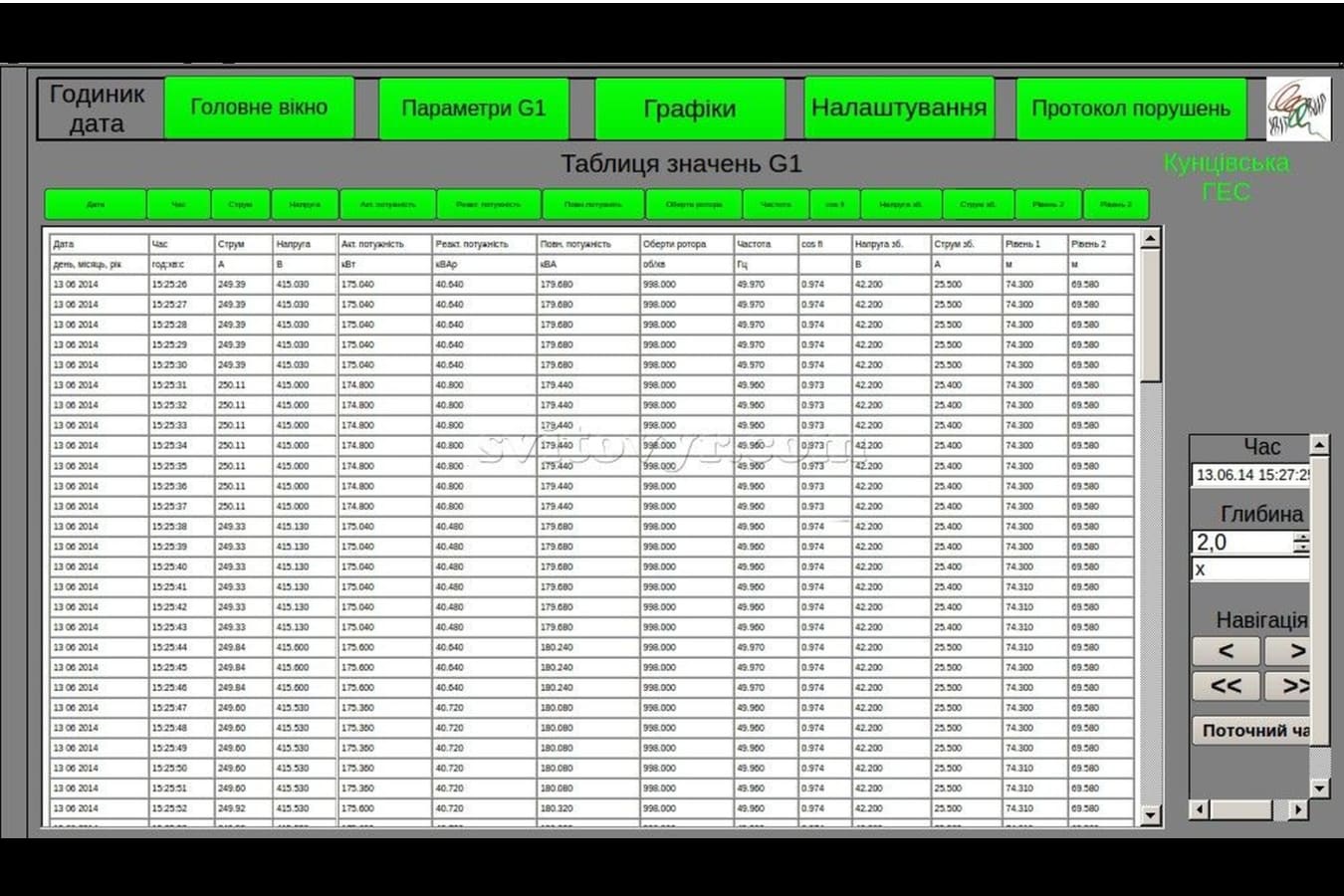
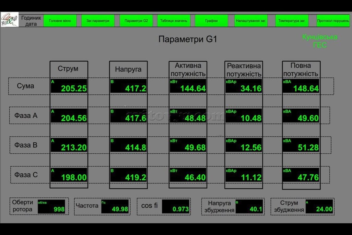
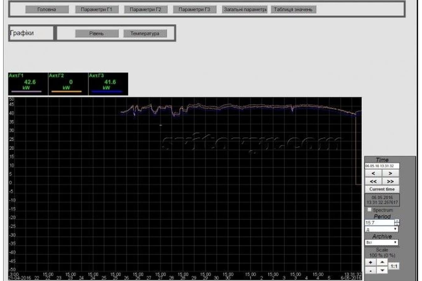
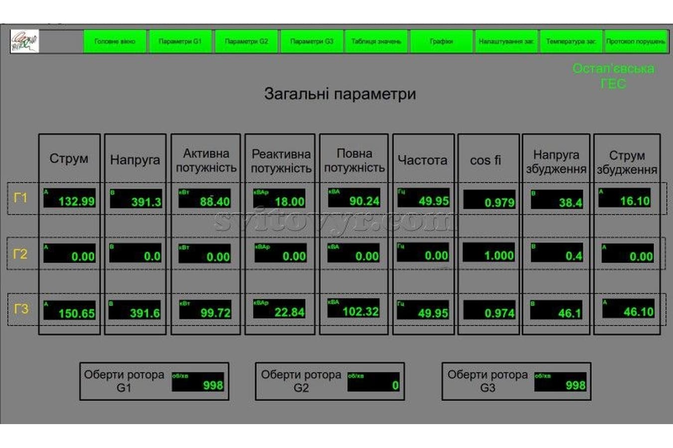
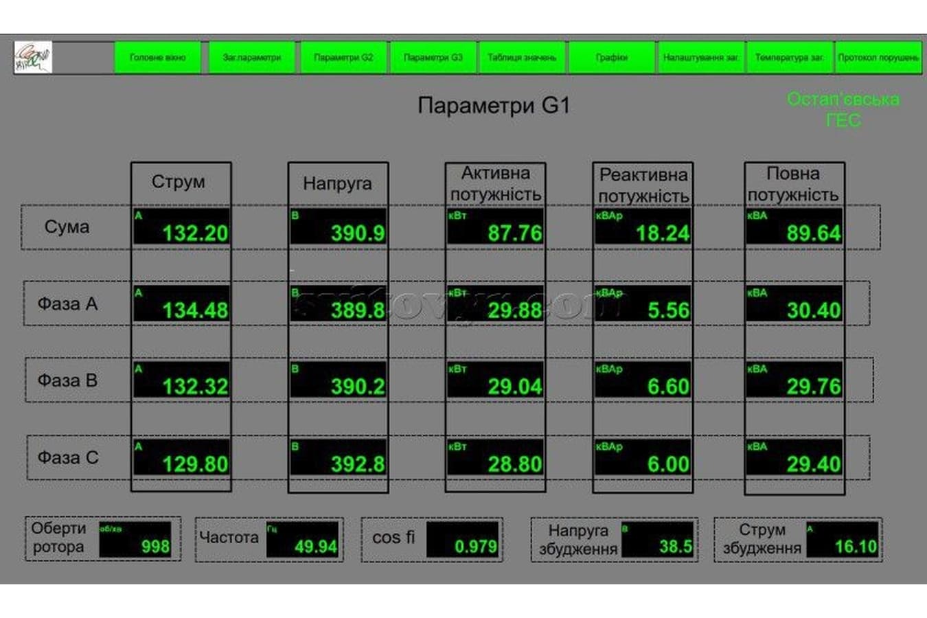
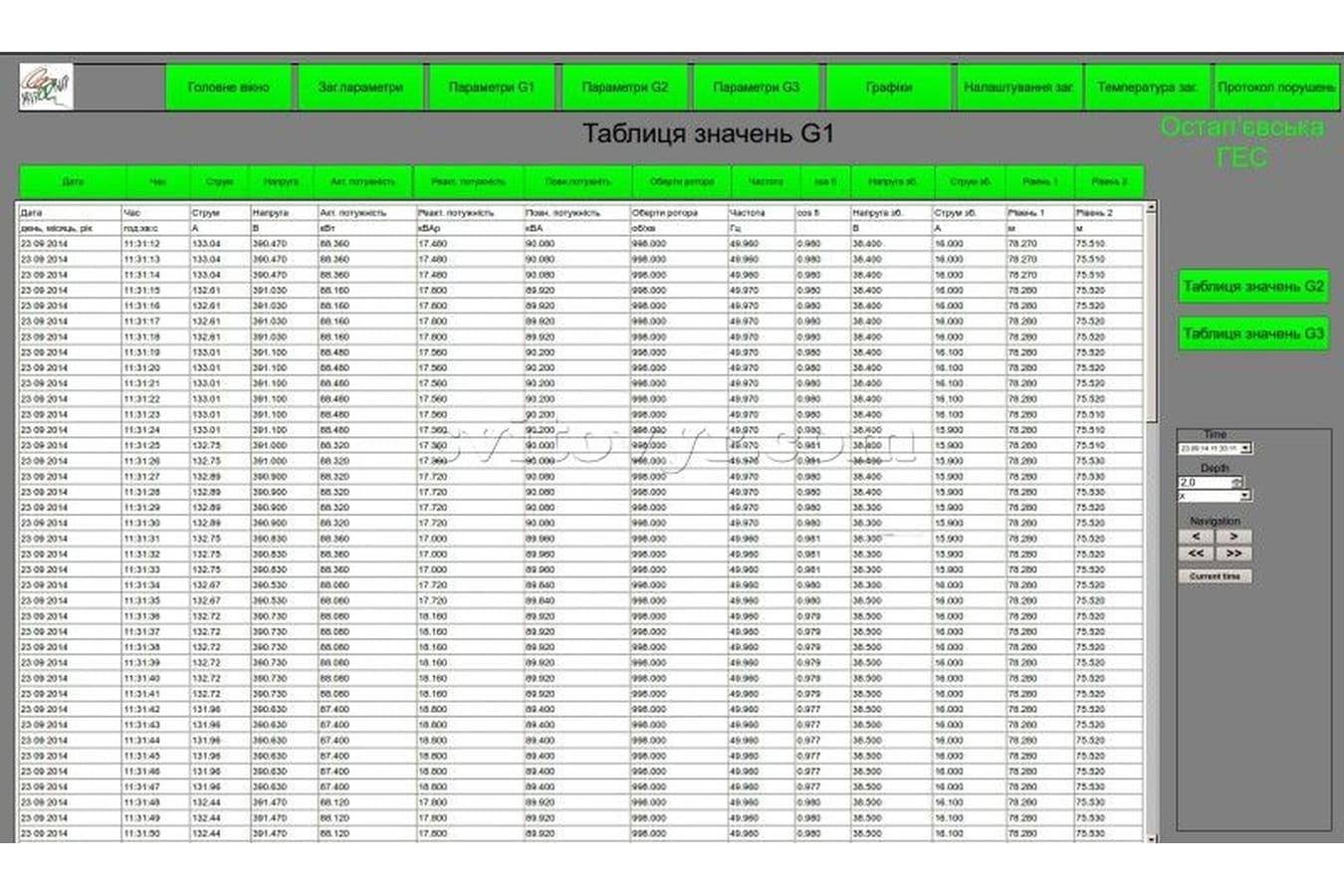
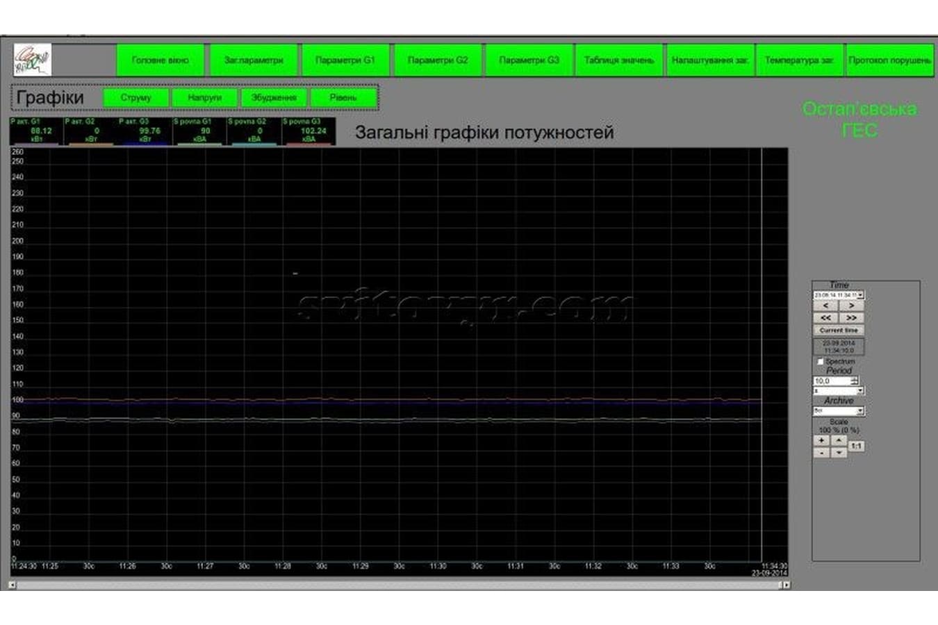
- through the communication channels: information from the digital multimeters (network parameters analyzers) on the values of the electric parameters of the generators.

A PLC processes the information obtained, defines the status of the system, establishes accident conditions and based on this processed information for both normal and emergency conditions provides:

- discrete signals to control switches and other commutation devices (relays etc) 

- analogue signals to control generator exciters and water drive feeds giving water to the generator turbine blades.

Measurement devices and converters

Electronic parameters of the generators are measured with DIRIS A40 (Socomec, France) digital multimeters with communication modules that transfer the obtained data to the PLC. These multimeters also show the information measured on digital displays.

Since people have better reaction to needle instruments rather than digital ones, needle analogue ammeters and alternating current voltmeters were used for visual presentation of the currents and voltages of the generators.

Controllers measure excitation currents and voltage of the generators by mean of measuring converters (ПНС-1, “PNS-1” – Microl, Ukraine) of direct currents and voltage into unified analogue signals. Magnetic ammeters and voltmeters are used to visually represent these values.

Measurements of temperatures of various zones of generator stators are provided by means of a special PLC module: a module of RTD analogue inputs and PT1000 platinum resistance thermometers (Termoprylad, Ukraine).

Excitement system

Controlled thyristor rectifiers are used as generator exciters (they are using step-down transformers from 0.4 kV busbars) that are known for their rapid reaction and are controlled by unified signals of 0..10 V direct voltage, enabling direct (with no additional conversion) control of the rectifiers from the controller analogue outputs.

Power ring protection

To provide generator-transformer line protection based on the element parameters, the abovementioned automatic switches have been used along with backup protection means such as fuses. The generating system is additionally protected by the PLC which receives measurement data and establishes emergency conditions. In the event of such conditions the PLC produces signals to switch off generators, close the generator turbine deflectors and block thyristors.

Water supply to turbine blades

Water supply control is provided by motor drives that are controlled by Altivar 312 frequency drives. Uninterruptible power supply is provided by means of gel batteries and a Xantrex inverter.

CONNECTING GENERATRORS TO THE NETWORK.

CircutorSynchroMAX (Circutor, Spain) automatic synchroniser was chosen for automatic synchronisation of generators with the network. It receives instant measurements of the voltage of the generator and the network, calculates effective voltages, frequency values and phase difference between the generator and the network voltages and gives signals to lower or raise generator frequency and to connect the generator to the network while taking into consideration the time of turning the switch on. 

Automatic synchroniser is turned on by the controller, which also connects measured signals of networks and generators values and is operating simultaneously with the automatic synchroniser. The signals to lower or raise the frequency and the signal to connect a generator to the network are transmitted from the generator to the controller which controls the voltage and frequency of an applicable generator and the operation of an applicable switch. 

Two ПНС-2 (“PNS-2”, Mikrol, Ukraine) converters were used to adjust the effective generator voltage accurately to the effective network voltage. They convert alternating current into a unified analogue signal (one is used for the network voltage and establishes the primary value and the other one is used for the generator voltage and establishes the adjusted value). 

Commutation devices connecting generators to the network are using automatic switches (Moeller, Austria) with motor drives that are highly reliable and also protect generators from current overload and short circuits.

SCADA Supervisory Control And Data Acquisition system
SCADA (Supervisory Control And Data Acquisition) system WinCC (SIEMENS, Gernamy) is used to visualise manufacturing processes, acquire and register measured data and information about the conditions of the devices, mechanisms and the systems in general.


SCADA application enables better adjustment, more accurate measured information, logs of statistical data on the normal routine operation parameters and emergency events. Analyzing this data helps predict the future system operation, understand the causes of emergency situations and prevent them from happening in the future.


IMPLEMENTED PROJECTS

Boryslavska HPP

THIS HPP IS UNDER CONSTRUCTION.


IMPLEMENTED PROJECTS

Buchach HPP


According to the terms of reference, there are two generators that must generate energy into the grid in the presence of mains voltage, as well as in the absence of mains voltage, work autonomously to ensure uninterrupted power to the monastery, its infrastructure and treatment facilities with a total capacity of 50 kW.

Since any of the generators can provide autonomous operation, and the higher efficiency for the declared power is in the smaller generator (80 kW), the control system provides autonomous operation only for the generator 1 (80 kW).

 The main decisive element of the station control system is the controller, which receives information from the transducers, processes it and outputs control signals to the actuators of the system. 

To measure the electrical parameters of the generators, Diris A20 digital multimeters from Socomec (France) are used, which measure all the electrical parameters of the generators, visually display them and transmit the measured information to the controller via the RS-485 interface.

Generator excitation systems consist of controlled thyristor rectifiers, which are characterized by high speed and are controlled by unified signals of constant voltage 0..10 V, which allows direct (without additional conversion) to control rectifiers from analog outputs of the controller.

Generator 1 has an additional independent excitation from the battery, which is connected to ensure autonomous operation until the voltage at the output of the thyristor rectifier 1.

Control of frequency and active power of station, is provided by turn of blades of turbines of generators. Actuators that rotate the blades of the turbine generators are a DC motor for generator 1 (80 kW, 100 kVA) and a hydraulic pump for generator 2 (200 kW, 250 kVA).

To control the connection of generators to parallel operation with the electrical network, the synchronization column "Eltika" SPE "Electroautomatics" (Ukraine) is used. 

The synchronization column measures the voltages and frequencies of the generators and the network, and provides the controller with signals for controlling the voltages and frequencies of the generators and a signal for connecting the generators to the network.


IMPLEMENTED PROJECTS

Zalozetska HPP

THIS HPP IS UNDER CONSTRUCTION.
TWO GENERATOR. BUILT IN 1949. IN THE EARLY 70'S IT WAS STOPPED.


IMPLEMENTED PROJECTS

Kuntsivska HPP

Kuntseve hydroelectric power station has two 250-kW synchronous generators, the established capacity amounts to 500 kW. Generation voltage amounts to 0.4 kV. Automatic operation system has been installed. The main station control device is a programmable logic controller (PLC).


A water feed deflector control of a hydro generator turbine has been replaced in the framework of Kunseve hydroelectric power station reconstruction. A thyristor voltage control was used for synchronous generator excitation. Hydro generator operation is controlled by means of an M258 PLC (Schneider-Electric).

Measurement devices and converters

Electronic parameters of the generators are measured with DIRIS A40 (Socomec, France) digital multimeters with communication modules that transfer the obtained data to the PLC. These multimeters also show the information measured on digital displays. 

Since people have better reaction to needle instruments rather than digital ones, needle analogue ammeters and alternating current voltmeters were used for visual presentation of the currents and voltages of the generators. 

Controllers measure excitation currents and voltage of the generators by mean of measuring converters (ПНС-11, “PNS-11” – Microl, Ukraine) of direct currents and voltage into unified analogue signals. Magnetic ammeters and voltmeters are used to visually represent these values. 

Temperatures of various zones of generator stators and slew drives are taken by means of Pt100 resistance thermometers and a converter to МВ-110 Modbus (Oven, Russia).

Connecting generatrors to the network

CircutorSynchroMAX (Circutor, Spain) automatic synchroniser was chosen for automatic synchronisation of generators with the network. It receives instant measurements of the voltage of the generator and the network, calculates effective voltages, frequency values and phase difference between the generator and the network voltages and gives signals to lower or raise generator frequency and to connect the generator to the network while taking into consideration the time of turning the switch on.

Automatic synchroniser is turned on by the controller, which also connects measured signals of networks and generators values and is operating simultaneously with the automatic synchroniser. The signals to lower or raise the frequency and the signal to connect a generator to the network are transmitted from the generator to the controller which controls the voltage and frequency of an applicable generator and the operation of an applicable switch.

Two ПНС-12 (“PNS-12”, Mikrol, Ukraine) converters were used to adjust the effective generator voltage accurately to the effective network voltage. They convert alternating current into a unified analogue signal (one is used for the network voltage and establishes the primary value and the other one is used for the generator voltage and establishes the adjusted value).

Commutation devices connecting generators to the network are using automatic switches (Moeller, Austria) with motor drives that are highly reliable and also protect generators from current overload and short circuits.

Excitement system

Controlled thyristor rectifiers are used as generator exciters (they are using step-down transformers from 0.4 kV busbars) that are known for their rapid reaction and are controlled by unified signals of 4.20 mA direct current, enabling direct (with no additional conversion) control of the rectifiers from the controller analogue outputs.

Power ring protection

Parametric (based on elements parameters) generator-transformer line protection is provided by means of a peak current protection relay АЛ-5 (AL-5) and НЛ-6 (NL-6), НЛ-11 (NL-11), ЕЛ-11 (EL11) voltage relays. The generating system is additionally protected by the PLC which receives measurement data and establishes emergency conditions. In the event of such conditions the PLC produces signals to switch off generators, close the generator turbine deflectors and block thyristors.

Connecting generatrors to the network

CircutorSynchroMAX (Circutor, Spain) automatic synchroniser was chosen for automatic synchronisation of generators with the network. It receives instant measurements of the voltage of the generator and the network, calculates effective voltages, frequency values and phase difference between the generator and the network voltages and gives signals to lower or raise generator frequency and to connect the generator to the network while taking into consideration the time of turning the switch on. 

Automatic synchroniser is turned on by the controller, which also connects measured signals of networks and generators values and is operating simultaneously with the automatic synchroniser. The signals to lower or raise the frequency and the signal to connect a generator to the network are transmitted from the generator to the controller which controls the voltage and frequency of an applicable generator and the operation of an applicable switch. 

Two ПНС-12 (“PNS-12”, Mikrol, Ukraine) converters were used to adjust the effective generator voltage accurately to the effective network voltage. They convert alternating current into a unified analogue signal (one is used for the network voltage and establishes the primary value and the other one is used for the generator voltage and establishes the adjusted value). 

Commutation devices connecting generators to the network are using automatic switches (Moeller, Austria) with motor drives that are highly reliable and also protect generators from current overload and short circuits.

SCADA Supervisory Control And Data Acquisition system

SCADA (Supervisory Control And Data Acquisition) OpenSCADA system (Ukraine). is used to visualise manufacturing processes, acquire and register measured data and information about the conditions of the devices, mechanisms and the systems in general. 

SCADA application enables better adjustment, more accurate measured information, logs of statistical data on the normal routine operation parameters and emergency events. Analyzing this data helps predict the future system operation, understand the causes of emergency situations and prevent them from happening in the future.

Station hydro generators can be operated in the following modes: 

1. Based on the water level (water level remains stable);
2. Based on the active energy (a generator produces a set amount of active energy kW); 
3. Based on the reactive energy (a set amount of reactive energy kVAr can be generated or power factor can be used); 4. Autonomous mode (operating without synchronization with the grid for the dynamic active load) (station in-house needs);
5. The generator can work alone as well as with other generators;
6. Manual local control (all operation modes can be regulated directly at the generator); 
7. Manual remote control (all operation modes can be regulated by a distribution board in the central control room); 
8. Automatic control ( with an HMI panel of generator operation board in the operation room and with the SCADA system by means of a computer from the operator’s room); 
9. Automatic remote control (by means of the WebServer through the Ethernet by means of WebBrowser).

Control of water feed to turbine blades

Control of water feed is realized by means of a deflector control based on a Slew Drive (IMO, Germany). The engine is set for direct current voltage and is powered by storage batteries; this solution allowed to operate the deflector machine even when the in-house voltage was out.


IMPLEMENTED PROJECTS

Krasnohutirska HPP

RECONSTRUCTION OF OWN NEEDS ON 0.4 KV SIDE


IMPLEMENTED PROJECTS

Novoshytska HPP

Three generators with a total capacity of 165 kW. Generators of asynchronous type. Siphon type turbines. Implemented SCADA top-level control system.

Control is carried out by means of PLC (programmable logic controller). WebServer provides the ability to manage and control the hydropower plant remotely. A video monitoring system has been installed.


IMPLEMENTED PROJECTS

Ostapievska HPP

Ostapievska hydroelectric power station has three 250-kW synchronous generators, but its turbines are 128 kW, the established capacity amounts to 384 kW. Automatic operation system has been installed. The main station control device is a programmable logic controller (PLC). A water feed deflector control of a hydro generator turbine has been replaced in the framework of Ostapievska hydroelectric power station reconstruction. A thyristor voltage control was used for synchronous generator excitation. Hydro generator operation is controlled by means of an M258 PLC (Schneider-Electric).

Measurement devices and converters

Electronic parameters of the generators are measured with DIRIS A40 (Socomec, France) digital multimeters with communication modules that transfer the obtained data to the PLC. These multimeters also show the information measured on digital displays. 

Since people have better reaction to needle instruments rather than digital ones, needle analogue ammeters and alternating current voltmeters were used for visual presentation of the currents and voltages of the generators. 

Controllers measure excitation currents and voltage of the generators by mean of measuring converters (ПНС-11, “PNS-11” – Microl, Ukraine) of direct currents and voltage into unified analogue signals. Magnetic ammeters and voltmeters are used to visually represent these values. 

Temperatures of various zones of generator stators and slew drives are taken by means of Pt100 resistance thermometers and a converter to МВ-110 Modbus (Oven, Russia).

Connecting generatrors to the network

CircutorSynchroMAX (Circutor, Spain) automatic synchroniser was chosen for automatic synchronisation of generators with the network. It receives instant measurements of the voltage of the generator and the network, calculates effective voltages, frequency values and phase difference between the generator and the network voltages and gives signals to lower or raise generator frequency and to connect the generator to the network while taking into consideration the time of turning the switch on. 

Automatic synchroniser is turned on by the controller, which also connects measured signals of networks and generators values and is operating simultaneously with the automatic synchroniser. The signals to lower or raise the frequency and the signal to connect a generator to the network are transmitted from the generator to the controller which controls the voltage and frequency of an applicable generator and the operation of an applicable switch. 

Two ПНС-12 (“PNS-12”, Mikrol, Ukraine) converters were used to adjust the effective generator voltage accurately to the effective network voltage. They convert alternating current into a unified analogue signal (one is used for the network voltage and establishes the primary value and the other one is used for the generator voltage and establishes the adjusted value). 

Commutation devices connecting generators to the network are using automatic switches (Moeller, Austria) with motor drives that are highly reliable and also protect generators from current overload and short circuits.

Excitement system

Controlled thyristor rectifiers are used as generator exciters (they are using step-down transformers from 0.4 kV busbars) that are known for their rapid reaction and are controlled by unified signals of 4.20 mA direct current, enabling direct (with no additional conversion) control of the rectifiers from the controller analogue outputs.

Power ring protection

Parametric (based on elements parameters) generator-transformer line protection is provided by means of a peak current protection relay АЛ-5 (AL-5) and НЛ-6 (NL-6), НЛ-11 (NL-11), ЕЛ-11 (EL11) voltage relays. 

The generating system is additionally protected by the PLC which receives measurement data and establishes emergency conditions. In the event of such conditions the PLC produces signals to switch off generators, close the generator turbine deflectors and block thyristors.

Control of water feed to turbine blades

Control of water feed is realized by means of a deflector control based on a Slew Drive (IMO, Germany). The engine is set for direct current voltage and is powered by storage batteries; this solution allowed to operate the deflector machine even when the in-house voltage was out.

SCADA Supervisory Control And Data Acquisition system

SCADA (Supervisory Control And Data Acquisition) OpenSCADA system (Ukraine). is used to visualise manufacturing processes, acquire and register measured data and information about the conditions of the devices, mechanisms and the systems in general. 

SCADA application enables better adjustment, more accurate measured information, logs of statistical data on the normal routine operation parameters and emergency events. Analyzing this data helps predict the future system operation, understand the causes of emergency situations and prevent them from happening in the future.

Station hydro generators can be operated in the following modes: 

1. Based on the water level (water level remains stable)
2. Based on the active energy (a generator produces a set amount of active energy kW)
3. Based on the reactive energy (a set amount of reactive energy kVAr can be generated or power factor can be used) 4. Autonomous mode (operating without synchronization with the grid for the dynamic active load) (station in-house needs)
5. The generator can work alone as well as with other generators.
6. Manual local control (all operation modes can be regulated directly at the generator)
7. Manual remote control (all operation modes can be regulated by a distribution board in the central control room).
8. Automatic control ( with an HMI panel of generator operation board in the operation room and with the SCADA system by means of a computer from the operator’s room)
9. Automatic remote control (by means of the WebServer through the Ethernet by means of WebBrowser)


IMPLEMENTED PROJECTS

Sandratska HPP


IS IN THE STAGE OF RECONSTRUCTION

Soborna HPP


IMPLEMENTED PROJECTS

Sutyska HPP


Sutyska HPP has two synchronous generators of 900 kVA, the installed capacity is 1800 kVA. Generator voltage 6 kV mains voltage 10 kV. The excitation system of hydrogenerators from mechanical type to thyristor type was replaced. The M221 PLC (Schneider-Electric, France) was used in the excitation system.

MEASURING DEVICES AND CONVERTERS

Measurement of electrical parameters of generators is provided by digital multimeters DIRIS A40 (Socomec, France), with the established communication modules thanks to which the information measured by these devices is transferred to the PLC. 
These multimeters also display the measured information on a digital display. Because humans respond better to handheld instruments than to digital ones, handheld analog ammeters and AC voltmeters are used to visualize generator currents and voltages. Measurement by the controller of currents and excitation voltages of generators is provided by measuring converters (PNS-11 - Mikrol, Ukraine) of direct voltages and currents in the unified analog signals and digital signals of Modbus RTU.
Magnetoelectric ammeters and voltmeters are used to visually represent these quantities.

CONNECTION OF GENERATORS TO THE NETWORK

CircutorSynchroMAX autosynchronizer (Circutor, Spain) is selected as the means of automatic synchronization of generators with the network. as well as the signal to connect the generator to the network, taking into account the time of switching on the switch.

The auto-synchronizer is switched on by the controller, and also the controller connects measuring signals of voltages of a network and generators which is switched on for parallel work to the auto-synchronizer. The signals to increase or decrease the frequency and the signal to connect the generator to the network are transmitted from the auto-synchronizer to the controller and the controller controls the voltage and frequency of the corresponding generator and the inclusion of the corresponding switch.

To accurately adjust the current value of the generator voltage to the current value of the mains voltage during synchronization, two converters PNS-12 (Microl, Ukraine) AC to a unified analog signal are used (one for the mains voltage - forms the setpoint, and for the generator voltage - forms the adjustable value).

EXCITEMENT SYSTEM

As exciters of generators the controlled thyristor rectifiers (included through step-down transformers from buses of own needs of station of 0,4 kV) which are characterized by high speed and are operated by the unified signals of a direct current of 4..20 mA that allows to control rectifiers directly (without additional conversion) are used. from the analog outputs of the controller.

protection of power circles

For parametric (based on the parameters of the elements) protection of the generator-transformer lines, the relay control of the EL-11 is used. The generation system is also protected by the PLC - on the basis of the received measuring information it generates accident states, in which case it emits signals to turn off the generators, close the guide devices of the turbine generators and to block the thyristor converters.

CONTROL OF WATER SUPPLY TO TURBINE BLADES

The water supply is controlled by a hydraulic regulator of the guide apparatus. At the station the regulation by hydrogenerators is realized in the following modes: By active energy (the generator produces a given amount of active energy kW).

By reactive energy (you can generate a given amount of reactive energy kVAr or using cosine fi). The generator can work as one or in pair with another generator.

Manual local adjustment (you can control all modes of operation of the generator directly next to it).


IMPLEMENTED PROJECTS

Sukhorabivska HPP

Sukhorabiv hydroelectric power station has three 250-kW synchronous generators, the established capacity amounts to 750 kW. Generation voltage amounts to 0.4 kV. Automatic operation system has been installed. The main station control device is a programmable logic controller (PLC). A water feed deflector control of a hydro generator turbine has been replaced in the framework of Sukhorabiv hydroelectric power station reconstruction. A thyristor voltage control was used for synchronous generator excitation. Hydro generator operation is controlled by means of an M258 PLC (Schneider-Electric).

Measurement devices and converters

Electronic parameters of the generators are measured with DIRIS A40 (Socomec, France) digital multimeters with communication modules that transfer the obtained data to the PLC. These multimeters also show the information measured on digital displays.
Since people have better reaction to needle instruments rather than digital ones, needle analogue ammeters and alternating current voltmeters were used for visual presentation of the currents and voltages of the generators.
Controllers measure excitation currents and voltage of the generators by mean of measuring converters (ПНС-11, “PNS-11” – Microl, Ukraine) of direct currents and voltage into unified analogue signals. Magnetic ammeters and voltmeters are used to visually represent these values.
Temperatures of various zones of generator stators and slew drives are taken by means of Pt100 resistance thermometers and a converter to МВ-110 Modbus (Oven, Russia).

CONTROL OF WATER FEED TO TURBINE BLADES

Control of water feed is realized by means of a deflector control based on a Slew Drive (IMO, Germany). The engine is set for direct current voltage and is powered by storage batteries; this solution allowed to operate the deflector machine even when the in-house voltage was out.


Excitement system

Controlled thyristor rectifiers are used as generator exciters (they are using step-down transformers from 0.4 kV busbars) that are known for their rapid reaction and are controlled by unified signals of 4.20 mA direct current, enabling direct (with no additional conversion) control of the rectifiers from the controller analogue outputs.

Power ring protection

Parametric (based on elements parameters) generator-transformer line protection is provided by means of a peak current protection relay АЛ-5 (AL-5) and НЛ-6 (NL-6), НЛ-11 (NL-11), ЕЛ-11 (EL11) voltage relays. The generating system is additionally protected by the PLC which receives measurement data and establishes emergency conditions. In the event of such conditions the PLC produces signals to switch off generators, close the generator turbine deflectors and block thyristors.

CONNECTING GENERATRORS TO THE NETWORK   

CircutorSynchroMAX (Circutor, Spain) automatic synchroniser was chosen for automatic synchronisation of generators with the network. It receives instant measurements of the voltage of the generator and the network, calculates effective voltages, frequency values and phase difference between the generator and the network voltages and gives signals to lower or raise generator frequency and to connect the generator to the network while taking into consideration the time of turning the switch on. Automatic synchroniser is turned on by the controller, which also connects measured signals of networks and generators values and is operating simultaneously with the automatic synchroniser. The signals to lower or raise the frequency and the signal to connect a generator to the network are transmitted from the generator to the controller which controls the voltage and frequency of an applicable generator and the operation of an applicable switch. Two ПНС-12 (“PNS-12”, Mikrol, Ukraine) converters were used to adjust the effective generator voltage accurately to the effective network voltage. They convert alternating current into a unified analogue signal (one is used for the network voltage and establishes the primary value and the other one is used for the generator voltage and establishes the adjusted value). Commutation devices connecting generators to the network are using automatic switches (Moeller, Austria) with motor drives that are highly reliable and also protect generators from current overload and short circuits.

SCADA Supervisory Control And Data Acquisition system

SCADA (Supervisory Control And Data Acquisition) OpenSCADA system (Ukraine). is used to visualise manufacturing processes, acquire and register measured data and information about the conditions of the devices, mechanisms and the systems in general.
SCADA application enables better adjustment, more accurate measured information, logs of statistical data on the normal routine operation parameters and emergency events. Analyzing this data helps predict the future system operation, understand the causes of emergency situations and prevent them from happening in the future.

Station hydro generators can be operated in the following modes:
1. Based on the water level (water level remains stable); 
2. Based on the active energy (a generator produces a set amount of active energy kW); 
3. Based on the reactive energy (a set amount of reactive energy kVAr can be generated or power factor can be used);
4. Autonomous mode (operating without synchronization with the grid for the dynamic active load) (station in-house needs);
5. The generator can work alone as well as with other generators; 
6.Manual local control (all operation modes can be regulated directly at the generator)
7. Manual remote control (all operation modes can be regulated by a distribution board in the central control room);
8. Automatic control ( with an HMI panel of generator operation board in the operation room and with the SCADA system by means of a computer from the operator’s room); 
9. Automatic remote control (by means of the WebServer through the Ethernet by means of WebBrowser).


IS IN THE STAGE OF RECONSTRUCTION

STORONYBABSKA HPP


IMPLEMENTED PROJECTS

Terebleritska HPP

Terebleritska HPP has three generators of 9 MW each, the installed capacity is
27 MW. Generation voltage 10.5 kV.

Generators are synchronous, with cascade excitation. Excitation regulation is automatic, by means of RVA-62 installations.

Manual adjustment of excitation by means of the motorized rheostat is also provided. 

Actually repair of these units on two generators was made by us.


IS IN THE STAGE OF RECONSTRUCTION

Ulvivska HPP


IMPLEMENTED PROJECTS

Tsybulivska HPP

A SYSTEM OF WATER LEVEL MEASUREMENT WAS DEVELOPED AT THIS HYDROPOWER PLANT


CRM-форма появится здесь

Feedback

If you are interested in our activities, you want to cooperate, or have specific questions - leave a request by filling out the form in the left column and we will be sure to contact you.

ADDRESS st. Danyla Apostola, 10/313, Lviv, Ukraine, 79040
MOBILE PHONE +380673334500